4×8 Plywood Sheet Yield Chart: Common Cut Sizes With Kerf
Compare no-kerf and 1/8-inch-kerf yields for common square and rectangular parts cut from a 48 × 96 inch plywood sheet.
A 4 × 8 plywood sheet is nominally 48 × 96 inches, but simple area division can overstate how many finished pieces fit. This chart compares the perfect no-kerf grid with a grid that reserves 1/8 inch between adjacent finished parts. It uses the full sheet as the usable rectangle, allows a 90-degree rotation, and adds no edge trim. Measure your actual stock and change those assumptions before purchasing material.
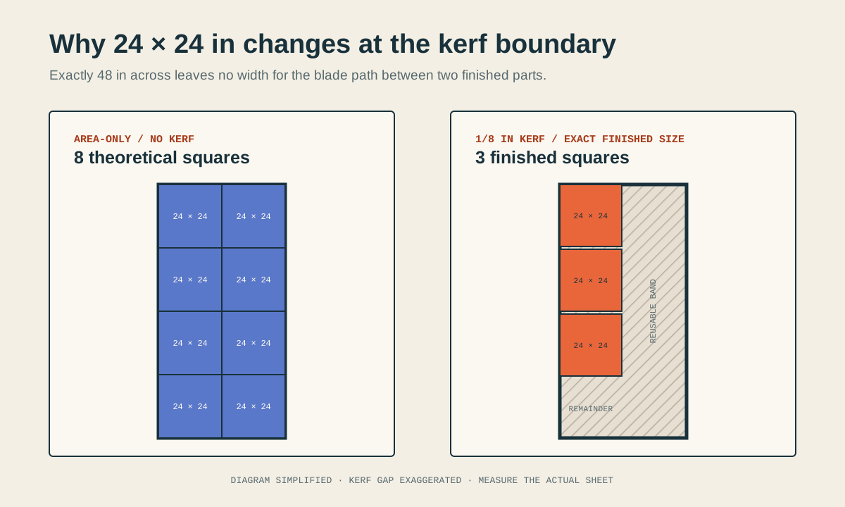
Quick answer: how many 24 × 24 pieces fit?
Ignoring blade width, a perfect 48 × 96 rectangle divides into eight 24 × 24 squares. That is a useful area check, but it is not a kerf-aware cutting result.
At a 1/8-inch kerf, two exact 24-inch finished squares across the 48-inch sheet need 48 1/8 inches: 24 + 1/8 + 24. That row does not fit. Only one square fits across and three fit along the 96-inch axis, so this strict grid returns three finished squares. An oversize sheet, smaller rough blanks, a different boundary strategy, or a thinner measured kerf can change the answer.
No-kerf grid: 2 across × 4 along = 8 piecesTwo finished widths plus one kerf: 24 + 0.125 + 24 = 48.125 in48.125 in required > 48 in sheet widthThis intentionally conservative example treats 24 inches as the required finished size and the sheet as exactly 48 × 96 inches.
Common 4 × 8 plywood yields with a 1/8-inch kerf
The no-kerf column is the geometric ceiling when the sheet dimensions divide cleanly. The kerf-aware column applies the same transparent grid formula used by the SawNest sheet yield calculator. Best grid describes the winning orientation across the 48-inch axis and along the 96-inch axis.
Finished-area yield is the area of the reported parts divided by 4,608 square inches. A lower percentage does not automatically mean the rest is trash: it can include continuous reusable offcuts that a mixed-part project may use well.
| Finished piece | No kerf | 1/8 in kerf | Best grid | Part-area yield |
|---|---|---|---|---|
| 4 × 4 in | 288 | 253 | 11 × 23 | 87.8% |
| 6 × 6 in | 128 | 105 | 7 × 15 | 82.0% |
| 8 × 8 in | 72 | 55 | 5 × 11 | 76.4% |
| 12 × 12 in | 32 | 21 | 3 × 7 | 65.6% |
| 16 × 16 in | 18 | 10 | 2 × 5 | 55.6% |
| 18 × 18 in | 10 | 10 | 2 × 5 | 70.3% |
| 24 × 24 in | 8 | 3 | 1 × 3 | 37.5% |
| 4 × 24 in | 48 | 33 | 11 × 3 | 68.8% |
| 6 × 24 in | 32 | 21 | 7 × 3 | 65.6% |
| 8 × 24 in | 24 | 15 | 5 × 3 | 62.5% |
| 12 × 24 in | 16 | 9 | 3 × 3 | 56.3% |
| 16 × 24 in | 12 | 6 | 2 × 3 | 50.0% |
| 18 × 24 in | 10 | 6 | 2 × 3 | 56.3% |
| 24 × 36 in | 4 | 3 | 1 × 3 rotated | 56.3% |
| 24 × 48 in | 4 | 3 | 1 × 3 rotated | 75.0% |
| 32 × 48 in | 3 | 2 | 1 × 2 rotated | 66.7% |
| 36 × 48 in | 2 | 2 | 1 × 2 rotated | 75.0% |
Reproduce any row with the grid formula
For one axis, add one kerf to the sheet and part dimensions, divide, and round down to a whole number. Repeat for the other axis and multiply the two counts. Then rotate the part 90 degrees, run both axes again, and keep the higher valid count.
For an 8 × 24 part, the entered orientation fits floor(48.125 ÷ 8.125) = 5 across and floor(96.125 ÷ 24.125) = 3 along. Five times three gives 15 pieces. The rotated grid fits only 11, so the entered orientation wins.
axis count = floor[(sheet axis + kerf) ÷ (finished part axis + kerf)]8-inch axis: floor(48.125 ÷ 8.125) = 524-inch axis: floor(96.125 ÷ 24.125) = 3The formula places kerf only between adjacent finished pieces. Edge trim is a separate allowance.
Measure stock before trusting a nominal 4 × 8 label
The chart uses an exact 48 × 96 inch usable rectangle. Real panels can be oversize, undersize, damaged, or out of square, and a project may need a clean reference edge. Measure the sheet, subtract any deliberate edge trim, and enter that usable width and length in the calculator.
Measure the blade-and-material setup too. A nominal blade description is not a measurement of the slot made by a particular machine, blade, alignment, and material. Small differences matter most at exact-multiple boundaries such as 12, 16, 24, and 48 inches.
- Lock rotation when visible face grain must run along one finished dimension.
- Treat rough blanks and exact finished parts as different planning inputs.
- Reserve edge trim explicitly instead of inflating every part dimension.
Use a grid for repeats and the optimizer for mixed parts
A full grid is fast, auditable, and appropriate when every required piece has the same rectangular dimensions. It does not mix orientations within one sheet, fill leftover bands with a second part size, or account for several material groups.
Use the interactive sheet yield calculator to replace the chart assumptions with your measurements. Use the full cut-list optimizer when the project contains different part sizes, per-part rotation rules, grain constraints, stock prices, or multiple sheets. In both cases, inspect the proposed geometry before turning it into a shop sequence.